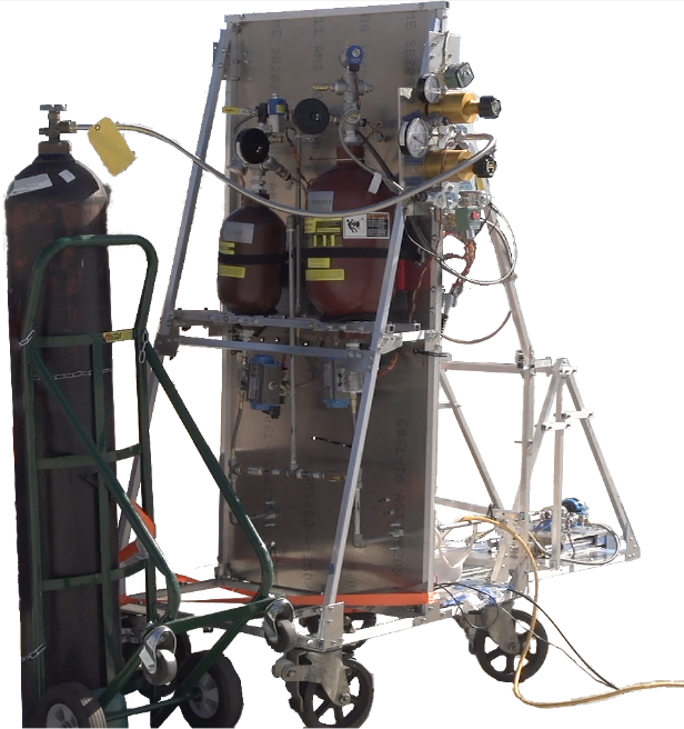
Yengine 1.0 (Yale Project Liquid)
August 2022 - May 2023
My role: Fluid Supply Specialist, focus on mass flow metering and testing procedures
Skillsets: Fluid mechanics, thermodynamics, CAD modeling, hardware construction
Objective:
Design and build a feed system to deliver desired quantities of Isopropyl Alcohol and Nitrous Oxide to a bi-propellant rocket engine injector.
Results:
Manufactured a functioning feed system which successfully delivered fluid in a water flow test (shown in video on the right).
Process:
When I joined this team upon my arrival at Yale, much of the design work for the feed system had been completed. However, there were still problems in the design process to be resolved, and the manufacturing process was yet to be undertaken. I focused on the following techniques and procedures:
CAD Modeling - The development of a CAD model for the feed system from the P&ID was essential for visualizing the system before its construction, especially with regard to how the system would be integrated to the test stand.
Flow Metering - Due to budgetary constraints, the team was unable to use flow meters capable of measuring the fluids in our system, so I developed an alternative method of characterizing flow through the system. By testing with water, measuring pressure at the top and bottom of the system, and considering various equations describing flow and pressure drop across orifices, we could develop curves to understand the nature of mass flow in the system and how changing the system affects the flow.
System Construction - The system was built using mostly NPT pipes, valves, and fittings, which involved heavy use of teflon tape and other standard leak-prevention methods.
Testing Procedures - The system would flow water, pressurized by nitrogen gas, through each line (Isopropyl Alcohol line and Nitrous Oxide line) separately, and then concurrently. The volume of water in each tank would be measured before use, and each tank would be emptied by each test.
Results & Discussion
The system functioned in flowing water safely; however, the construction and testing processes revealed some shortcomings in the design process. Most notably, the system had several leaks as a result of orientation-related issues in the construction process. Those facets which could be improved have inspired a new iteration, the development of which I have become a leader of: the Yengine 2.0
Piping & Instrumentation Diagram (P&ID) for the Yengine 1.0 Feed System
Data retrieved from water flow test


CAD model of the Yengine 1.0 feed system and test stand
Fully constructed Yengine 1.0 on the engine test stand
A close-up photograph of some feed system components during construction

